After all these years of painting indoors without proper ventilation, I finally decided to put myself first and bought a spraybooth.

I was actually thinking of building one, but I figured the stress and effort it would take is not worth it. And as I grow older, convenience is a luxury. So I said, "to hell with it" and with my eyes closed I placed an order from WGH Hardware from shopee.
The booth itself is pretty good. I initially thought that since it uses 2 fans, the sucking power to be weak, but boi, I tell you, it's pretty strong. It's pretty loud too. The top, base, and sides fold up when not in use to save a little bit of space.

|

|

So into Fusion360 we go. After taking some measurements, I now need to know how to use the loft feature. It was simple enought that after one 5 minute tutorial, I was already in the right track.
 |
 |

With enough experience in CAD and 3D printing, you would eventually figure out how to model for printing. For this one, there are tabs that go in the top and bottom, and a pin that goes to the side. You can't really design that into the model. I mean you can (we have free will), but for 3D printing, I would strongly recommend not to for the reasons I will mention below.
1. Designing the model with these tabs/pins in place would force your slicer to create support on the bottom.

 |
| since the tab protrudes away from the mouth, it is raised so only the tab is touching the build plate |

As only the tabs, or if you wanted to, you can also extend the pins to the same height so there will be 4 contact points with the bed - even so, this will still increase the risk of the model falling over due to bed adhesion.
2. The tabs and pins will likely be the first point of failures because of the orientation it is printed on.
 |
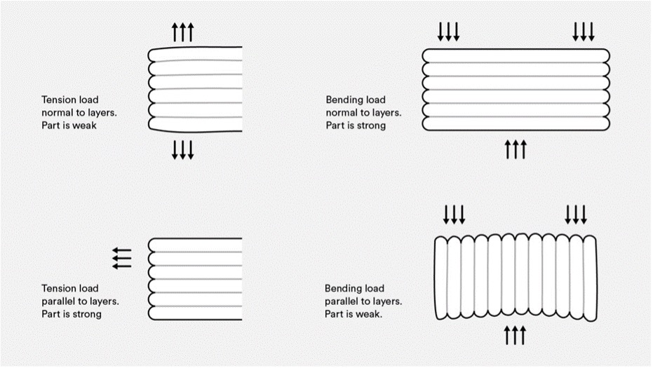 |
| this explains it better. lol Photo is from protolabs.com |
Because it will be printed like this, any perpendicular force would make the layer lines break first. And we don't want that - especially for any functional part.
So, in my design, I separated the tabs and pins so I can print and add them separately. This makes printing the main body easier as it will only support the tube, and it will also make sure that we print the tabs and pins in a way that maximizes their print orientation.
 |
| wow i did such a good job doing the layout in MS Paint |
The tabs and pins were printed laying on their side, so the layer lines are parallel to the length of the object.

|

|
I usually print a small section of the model to test the fit, but I don't know, I felt confident about this one and I just sent it. lol. Thankfully, all of the pieces fit. (not really hahah) The tabs were too short and would not lock properly to the rollers inside the booth, so I had to heat them with a lighter and pull them ever so slightly to extend them.
And I didn't use glue to attach them, I "welded" the tabs and pins together into the main body. 


I will let you in on a little secret.. You see that line over there? I actually broke it while testing the tabs. 😇 When I yanked it out of the spray booth, the layer lines gave and it broke almost in two pieces. I glued them quickly with super glue and then decided to pass it over with a soldering iron to reinforce it a bit more. So now you see the importance of print orientation, am I right? 😏


I will let you in on a little secret.. You see that line over there? I actually broke it while testing the tabs. 😇 When I yanked it out of the spray booth, the layer lines gave and it broke almost in two pieces. I glued them quickly with super glue and then decided to pass it over with a soldering iron to reinforce it a bit more. So now you see the importance of print orientation, am I right? 😏
 |
| even now I am amazed. |
 |
| almost the same foot print as the original, but now it directs up |
 |
| oh my goodness am I good or what |
Aight, I'mma let myself out. Have a nice one! Cheers!


No comments:
Post a Comment